
Could Incorrect Blast Room Calculations Cause Capacity Shortfalls and Costly Redesigns?
Underestimating Sand Blasting Room dimensions, airflow, or dust extraction capacity can restrict workpiece movement, create poor visibility, increase dust leakage, and overload filtration equipment. Oversizing the system, however, raises fan power, ducting, construction, and operating costs. A calculation-based proposal helps buyers coordinate technical parameters, budgets, and installation requirements before ordering.
The correct Blast Room design starts with the maximum workpiece envelope, required clearance, operator method, air change target, negative pressure, and dust-loading rate. Our Manufacturer provides Customizable OEM and ODM solutions, using coordinated room, ventilation, and dust collection calculations to support accurate budgeting and reliable project implementation.
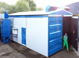
Start with Workpiece Size and Operating Clearance
Sand blasting room size calculations should begin with the largest workpiece, not with a standard room model. Measure the maximum length, width, height, weight, loading orientation, and handling method. The final internal room size must also accommodate operators, blasting hoses, protective equipment, lighting, ventilation flow, inspection access, and maintenance activities.
Basic room-size calculation
For a manually operated Blast Room, use the following preliminary logic:
Required room length = workpiece length + loading clearance + operator clearance + maintenance clearance
Required room width = workpiece width + side working clearance + airflow and access allowance
Required room height = workpiece height + overhead clearance + lighting and ventilation allowance
The clearance value depends on the handling method and process. A workpiece rotated by a crane may require more loading space than one placed on a fixed trolley. A Supplier should also check door dimensions, floor loading, crane coverage, trolley paths, emergency exits, and the space required to replace filters or service blast equipment.
Preliminary clearance checklist
- Measure the largest workpiece in its actual blasting orientation.
- Allow safe movement around all accessible workpiece surfaces.
- Include hose bending radius and operator retreat space.
- Reserve clearance for doors, lighting, duct connections, and inspection.
- Confirm loading equipment dimensions and lifting height.
- Check whether multiple workpieces will be blasted in one batch.
- Prevent workpieces, fixtures, or abrasive piles from blocking airflow paths.
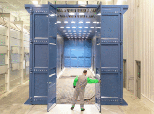
Calculate Room Volume and Required Airflow
After establishing the internal dimensions, calculate the room volume:
Room volume V = length × width × effective height
Use the effective internal volume rather than the external building dimensions. Fixed equipment, platforms, workpiece fixtures, and other permanent obstructions may reduce usable air volume. The design institute or ventilation engineer can then select an initial air change rate based on the abrasive process, dust generation, room leakage, operator method, and applicable workplace requirements.
Airflow calculation formula
A preliminary airflow estimate is:
Required airflow Q = room volume V × air change rate N
When V is expressed in cubic meters and N is expressed as air changes per hour, Q is obtained in cubic meters per hour. Convert the result to cubic meters per minute when comparing fan and dust collector ratings:
Q in cubic meters per minute = V × N ÷ 60
For example, a room with an effective volume of 240 cubic meters and a preliminary air change rate of 20 changes per hour requires:
240 × 20 ÷ 60 = 80 cubic meters per minute
This is a preliminary estimate, not a final equipment selection. The actual value must be checked against room leakage, door operation, abrasive loading, duct resistance, filter loading, make-up air, and required negative pressure.
| Calculation item | Formula or input | Purpose |
| Room volume | Length × width × effective height | Establishes the ventilation basis |
| Airflow | Volume × air changes per hour ÷ 60 | Provides a preliminary fan requirement |
| Negative pressure margin | Exhaust airflow compared with make-up airflow | Controls dust migration to the workshop |
| Collector selection | Required airflow plus system resistance margin | Maintains performance during filter loading |
Select Dust Collection Airflow from Process Conditions
Dust collection airflow selection should not rely only on the room volume. The collector must capture dust generated by blasting and maintain the intended airflow direction. The calculation should consider the number of active operators, abrasive consumption, workpiece surface area, room openings, recovery equipment, and the location of extraction points.
Dust collection capacity selection steps
- Calculate the preliminary room airflow using volume and air change rate.
- Estimate dust generation from abrasive type, blasting pressure, nozzle quantity, and operating hours.
- Check whether the room uses a full-floor recovery system, side extraction, ceiling supply, or another arrangement.
- Calculate duct pressure loss, elbows, transitions, filters, dampers, and exhaust-stack resistance.
- Add an engineering margin for filter loading, leakage, and future operating variation.
- Select a dust collector and fan that can deliver the required airflow at the calculated static pressure.
- Verify emissions, noise, power consumption, filter area, and dust-disposal requirements.
A dust collector with a high free-air rating may deliver insufficient airflow after ducts, filters, and dampers are installed. Request a fan curve showing airflow at the actual operating static pressure. The proposal should also state whether the quoted capacity is rated before or after filter loading and whether the system includes automatic cleaning.
Verify Negative Pressure and System Capacity
Negative pressure airflow calculations should balance containment and operating performance. Exhaust airflow generally needs to exceed controlled make-up airflow by a defined amount so that contaminated air does not escape when doors, seals, or access points are used. Excessive negative pressure can make doors difficult to open, increase energy consumption, and disturb blasting visibility.
- Define the target pressure difference between the Blast Room and workshop.
- Calculate make-up air through designed inlets, doors, gaps, and pressure-relief paths.
- Set exhaust airflow to maintain containment under normal operating conditions.
- Use pressure sensors and alarms to identify fan, filter, or duct problems.
- Confirm that make-up air does not create turbulence or push dust toward operators.
- Test pressure and airflow with clean and loaded filters where practical.
Dust collection system capacity verification
During commissioning, verify airflow at the collector inlet, extraction points, and exhaust outlet. Record static pressure, room pressure, filter differential pressure, fan speed, motor load, and emission performance. Compare measured values with the approved design calculations. If the room cannot maintain negative pressure or required visibility, correct the system before production acceptance.
The Manufacturer should provide airflow calculations, fan curves, duct layouts, filter specifications, electrical loads, control logic, and commissioning procedures. These documents allow the buyer, Supplier, design institute, and installation contractor to coordinate interfaces without relying on undocumented assumptions.
Conclusion
Accurate Blast Room sizing requires coordinated workpiece clearance, room volume, air change rate, negative pressure, duct resistance, and dust-loading calculations. Contact our team for a Customizable OEM or ODM preliminary proposal with verified airflow, capacity, and budget parameters for your project.
 English
  Russian
  Spanish
  Portuguese
  French
  Indonesian
  Thai
Thai